

Mass production of parts: why choose plastic injection molding?
Plastic injection, also known as injection molding, is a process for transforming thermoplastic materials.
Series production: the concept of plastic injection moulding
This process is particularly well-suited to mass production, and can be used for all types of series, from a few hundred parts upwards.
Mould sizing is based on the annual quantity to be produced:
- Number of impressions (=number of parts produced per casting)
- Quality and hardness of steel used
Processing is based on the principle of plasticizing the material, which is introduced in granules and injected under high pressure into the mold.
Economic and technical interests
Injection molding offers both economic and technical benefits. The material is relatively inexpensive, manufacturing times are short and the result is high quality. A plastic part made using this process will benefit from a suitable surface finish (mirror-polished or grained surfaces), without the need for retouching, and with a good weight/mechanical properties ratio.
Plastic injection molding offers a wide variety of shapes. The variety of materials also makes it possible to produce appearance and technical parts.
How does plastic injection molding work?
The transformation of mass-produced parts by plastic injection is carried out using an injection molding machine, which produces finished objects.
An injection molding machine consists of 2 main parts:
The plastic material, in granulated form, is first fed into the hopper of the injection molding machine.
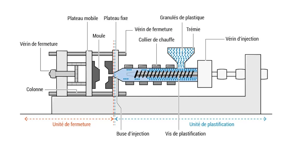
Right: laminating unit
An endless screw, in a heated sheath, placed under the hopper, rotates and thus advances the material to the end of the screw. The granules are melted along the way, to produce a homogeneous material with the right viscosity at the end of the screw. This phase of conveying the material to the end of the screw is called batching.
Sheath temperature depends on the material. From 180 degrees to over 300 degrees for some materials.
The piston transfers the material from the end of the screw to the inside of the mold.
The material then passes through an injection nozzle, a mechanical element linking the injection screw to the mold.
Injection pressure at the screw end can range from 800 to over 3,000 bar.
Once the material has been injected into the mold, it cools by shrinking around the core cavity. Once the part has reached a sufficiently low temperature, a set of ejectors (fine metal cylinders that translate independently of the cavities, generating the little circles we often see on plastic parts!) is activated to eject the part from the mold. The part may be picked up by an operator or robot, or fall loose into a packaging unit.
The mold can then be closed again and the next cycle started (dosing takes place partly in masked time during cooling/opening and part ejection).
Left: clamping unit
Injection pressure generates a force tending to open the mold at its parting line.
To counteract this force, the clamping unit uses a system of hydraulic cylinders and kneepads to keep the mold closed. The term “press tonnage” (e.g. 80 tonnes, 150 tonnes, 500 tonnes) is a misnomer and refers to the maximum clamping force of the press (e.g. 150 tonnes of clamping corresponds to ~1500 N of force).
The theoretical clamping force required is calculated by multiplying the projected surface area of the injected parts (per molding) by the material pressure.
Example:
Material injected at a theoretical pressure of 800 bar
A 2-cavity mold, with a projected area per part of 100cm2
The theoretical locking pressure is equal to : (800 x 100 x 2 (2 cavities) )/1000 x 1.15 (safety factor) = 18
The structure of a plastic injection mold
The mold is an indispensable element in the manufacture of finished objects by plastic injection molding. Also known as tooling, it is used to shape the plastic into its final form.
Tooling can weigh from a few hundred kg to several tons, and consists of a carcass and cavities. The cavities are the heart of the mold, the molding part of the product.
The carcass is the envelope that houses these cavities and ensures all the indispensable functions of the mold:
- Press clamping
- Injection channels
- Control circuits
- Ejector plates etc.
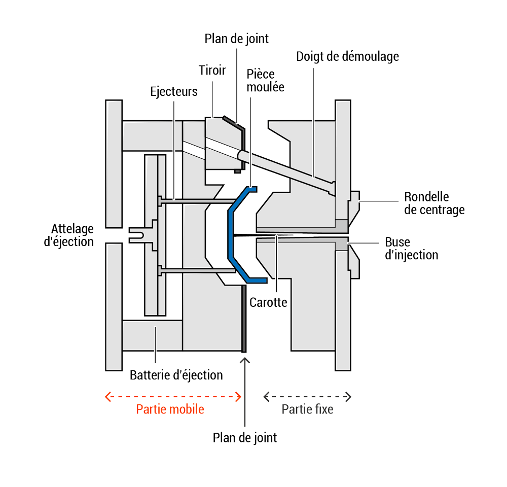
The tooling used to manufacture a plastic part is divided into two main parts. The first part of the mold is fixed, while the second is movable, to enable the tooling to be opened and the manufactured part to be ejected.
Schematically speaking, it sounds simple! But injection molding is a complex tool for many reasons:
- The dimensioning of injection functions (dimensioning of channels, injection points) is essential to the feasibility and quality of the part.
- In the same way, the mould temperature maintenance channels must be correctly positioned and sized.
It’s essential to take these rheological and thermodynamic aspects into account!
What’s more, the impressions are a puzzle of dozens or even hundreds of precision-machined mechanical parts. There are many stages involved, from the creation of impression blocks and pavers, to rough machining, wire-cutting, heat treatment and erosion.
The fitting phases (the assembly of all the pieces of this metal puzzle!) are meticulous and require a great deal of experience on the part of the mould maker.
Mechanical elements (enabling the molding of undercut shapes) present an additional difficulty, since these parts are in motion and need to be perfectly adjusted and designed to ensure repeated movements.
Characteristics of an injected part
The appearance of parts produced by plastic injection molding presents a number of special features. An injection-molded part presents four typical features of this process: an injection point, ejector marks, parting lines (main and secondary) and draft.
Each of these features has a specific purpose. Thus, the injection point marks the entry of the material into the part. Ejector marks are due to the ejectors being flush with the cavities. The main parting line corresponds to the location of the mold closure (fixed and moving parts). The secondary parting lines are due to the drawers, rising wedges used to produce undercut shapes. Finally, the undercuts help to remove the plastic part from the tool without damaging it.
The injection point
Every injected part has an injection point. It marks the point where the injection nozzle has introduced the plastic material into the tooling. The injection point is often shaped like a web or a small pin. It can be located in the center of the part, or on an outer edge. The design of the tooling to be used in the manufacturing process must take the injection point into account, to decide on its appearance and location. This aspect and location are not based solely on aesthetic criteria. The correct positioning and dimensioning of the injection channels and the injection point will determine how well the mold is filled.
A central location of the injection point will help to balance pressures during injection. This solution also helps optimize tool dimensions. It does, however, have a number of drawbacks, notably aesthetic: the sprue is more difficult to cut on molds not equipped with a hot nozzle. The use of a hot nozzle or hot block solves the problem, but this costly option can only be justified for large quantities.
When the injection point is positioned on the edge of the part being manufactured, the injection channel is easier to cut, often automatically when the mold is opened (this is known as a submarine injection point). This type of injection point also makes it possible to produce multi-cavity molds more cheaply, and to have an underwater point for automatic de-scrapping. There are a few points to be borne in mind, however: the mold needs to be properly balanced to ensure even filling.
In particular, the end of the filling process is of prime importance: you must avoid filling areas of the mold too early in relation to the rest of the mold. This would lead to overcompacting of the material in these areas, resulting in deformation, burrs, brittleness, etc. All this can be simulated using rheology software. All this can be simulated using rheology software.
Ejector tracks
With the plastic injection method, the material used is subjected to very high pressures when injected into the tooling. It is compressed and shrinks by 0.5% to 3.0% as it cools, tightening on the central core. To remove the part from the mould, ejectors controlled by the ejection battery push it out of the tool.
Cut-outs in the mold cavity allow these ejectors to pass through. A cut in the steel necessarily produces a trace on the injected plastic part. These small marks are often circular or rectangular. It’s important to know where the ejector marks are going to be, whether to ensure that the part looks good or to guarantee its technical properties. Other ejection solutions are possible, such as de-veining plates, compressed-air ejection or side drawers. However, these methods are more costly and should be reserved for very specific cases.
Parting lines
The different parts of the tooling meet to form a line on the plastic part. This is called the parting line. This fine, continuous line runs all the way around the part.
Mould design must therefore take the parting line into account. Particularly in the case of an appearance part, it’s important to find the ideal location so that it’s as inconspicuous as possible. It can, for example, be placed on the base of the part if the latter is not visible. It can also be blended in between two surface finishes, or placed over a simple decorative bulge. Depending on the part, deciding where to place the parting line will therefore be more or less complex. In order to make the best choice, the moldmaker must take into account the part’s intended use.
The remains
Remains are angles placed on the faces of the plastic part. They enable good demolding by reducing friction. As the material shrinks, it is subjected to the core of the mold and, in the absence of remains, the part will be difficult to extract without being deformed, broken or scratched.
A remain generally forms an angle of between 1.0° and 5.0°. Its exact size will depend on the material used, the texture, the dimensions of the part and the ejection method chosen. Draft angles must be considered at the design stage.

How to successfully industrialize your connected object?
Industrialization is a key stage in the development and production of an electronic product. In this guide, our experts have put together 16 key points to help you understand what’s at stake in this phase.
Plastic injection molding at Altyor
We have a workshop at our Altyor Shanghai plant, and a network of injectors in France and Europe.
Our Shanghai workshop can inject a wide variety of materials: ABS, PC, PP, PA, etc.
tonnages from 80 to 500 t